Summarize:
.jpg)
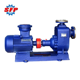
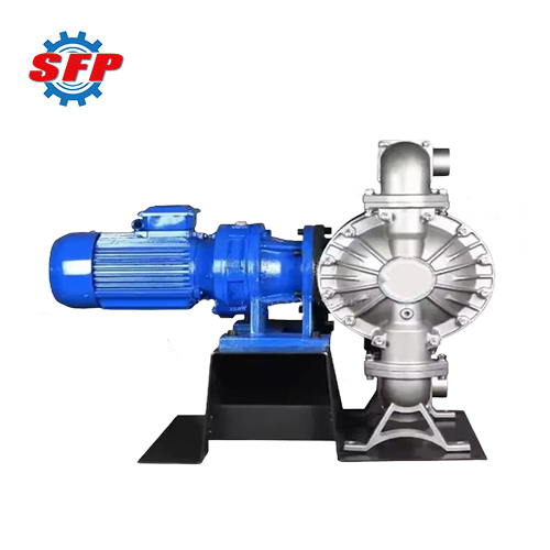
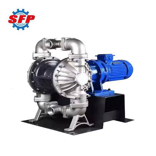
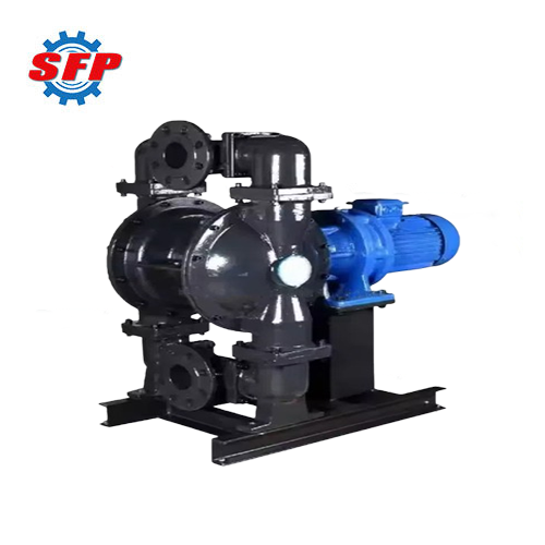
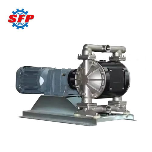
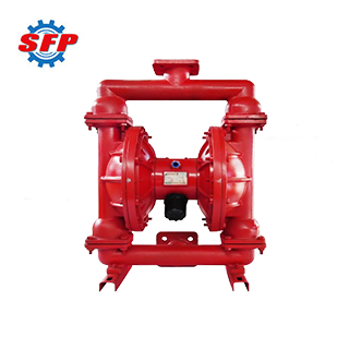
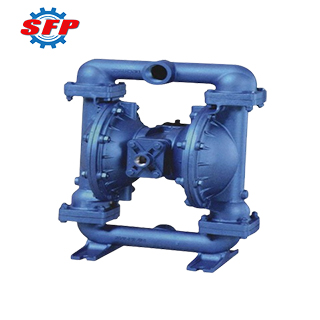
DBY series stainless steel diaphragm pump is a pneumatic diaphragm pump designed to handle various corrosive liquids, particulate-containing media, high-viscosity, volatile, flammable, and highly toxic liquids, as well as special liquids such as ceramic glaze slurry, fruit pulp, and adhesives. This pump combines the advantages of self-priming pumps, submersible pumps, slurry pumps, and other conveying pumps, featuring stable operation, excellent self-priming performance, wide application range, low vibration, and low noise.
Product Details:
DBY series diaphragm pumps feature two symmetrical working chambers, each equipped with an elastic diaphragm. The two diaphragms are interconnected via a connecting rod. Compressed air enters the air distribution valve through the pump's air inlet port and is then directed into one of the chambers via the air distribution mechanism. As the diaphragm in that chamber moves, the gas in the other chamber is expelled. At the end of the stroke, the reciprocating motion of the diaphragm causes the volume of the working chamber to change, forcing the two ball valves to alternately open and close, thereby achieving continuous suction and discharge of the liquid.
Application:
1. This pump can be used to treat sewage and waste oil in drainage ditches and sewers.
2. It can be used to transport liquids such as cyclopentane, sodium sulfite solution, and benzene.
3. This equipment can transport various highly toxic, flammable, explosive, and volatile liquids, as well as strong acids, strong alkalis, and corrosive liquids.
4. For the gas residues and acidic water that need to be centrally treated at the bottom of refineries, our diaphragm pumps can also meet their transportation requirements.
Feature:
1. The valve structure of the pneumatic diaphragm pump eliminates the “O”-ring and piston valve structures found in traditional valves. It adopts a three-way pilot-operated design, eliminating valve sticking points and pump shutdown phenomena.
2. The use of a simple pneumatic directional control valve design avoids the high downtime costs associated with shutdowns. Replacing pneumatic directional control valve components does not require disassembly of fluid components.
3. It provides the correct reverse signal to prevent shutdown, with faster reverse speed, resulting in high pump flow, excellent delivery performance, minimal pulsation, and stable flow.
4. The sliders inside the valve are made of durable materials, resistant to damage, ensuring smooth airflow and flexible directional switching.
Performance Data:
|
Model
|
Flow
(m³/h)
|
Allowable Particle Diameter
(mm)
|
Use Temperature ℃ |
Motor Power
(KW)
|
|
Cast Iron
|
Stainless Steel
|
|
DBY-10
|
0.5
|
1
|
90
|
150
|
0.37
|
|
DBY-15
|
0.75
|
1
|
90
|
150
|
0.5
|
|
DBY-25
|
3.5
|
2.5
|
90
|
150
|
1.5
|
|
DBY-40
|
4.5
|
2.5
|
90
|
150
|
1.5
|
|
DBY-50
|
6.5
|
3
|
90
|
150
|
2.2
|
|
DBY-65
|
8
|
4.5
|
90
|
150
|
2.2
|
|
DBY-80
|
16
|
8
|
90
|
150
|
4
|
|
DBY-100
|
20
|
8
|
90
|
150
|
4
|


.jpg)